Content Navigator
- What are Motor Shafts?
- What are the types of motor shafts?
- Challenges with Motor Shafts
- Maintenance Tips for Motor Shafts
What are Motor Shafts?

The motor shaft is an integral part of the motor and the link for electromechanical energy conversion between the motor and the device. They consist of cylindrical components that transmit power from the motor’s stator to its rotating output, support the rotating part, transmit torque, and determine the relative position of the rotating part to the stator. So, what exactly is a motor shaft?
The motor shaft acts as the shaft for the rotor, facilitating rotation when power is supplied to the stator windings. It provides structural support for rotor components such as bearings or pulleys and transmits torque from the output. Depending on their use and design, motor shafts can have straight or tapered threads at one end for connection purposes. In addition, engineers may opt for openwork designs to reduce weight without sacrificing strength or stiffness.
What are the types of motor shafts?
Motor shafts play a key role in the operation of many different types of machinery. These components are an integral part of nearly any mechanical system, from industrial motor shafts used in factory settings to miniature motor shafts in consumer electronics. Demystifying the mystery behind motor shafts can help you better understand what they do and choose the right type for your application.
—Classified according to whether there is a step on the shaft
-
Optical shaft and stepped shaft
- The optical shaft is usually made of cold-drawn round steel, which can reduce the man-hours of machining the outer circle of the shaft, and is sometimes used for micro motors.A stepped shaft allows for easy and safe mounting of many different parts and is why most motors use this type of shaft. The stepped shaft can be divided into one-way stepped shaft (the diameter of the step decreases gradually from one end to the other end) and two-way stepped shaft (the diameter of the step decreases gradually from the middle to both ends) according to the direction of the step.
—Classified according to the shaft blank manufacturing method
- Steel shafts (shafts processed from hot-rolled round steel), forged shafts (shafts made from forgings) and welded shafts (shafts welded with radial ribs)
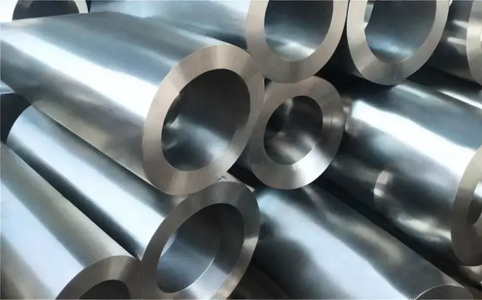
- Shafts made of hot-rolled round steel are the most common shafts in small and medium-sized motors. The material of the shaft is generally 45 high-quality carbon structural steel. For small power motors, some use Q235 ordinary carbon steel. The diameter of the blank should be selected according to the maximum diameter of the shaft plus the machining allowance. So the cutting volume is relatively large.Shafts with a diameter exceeding 100 mm should use forged shafts. Forged steel has high mechanical strength, and the stepped shaft has a rough shape, saving raw materials and cutting time. For large shafts requiring high mechanical strength, such as those of turbine generators, alloy steels are usually forged.
Challenges with Motor Shafts

Several common problems and cause analysis of the motor shaft during use
1# broken shaft
The broken shaft of the motor mostly occurs at the root of the shaft extension and the root of the bearing position at the end of the shaft extension.
If there is a shaft fracture phenomenon in the motor, macroscopic observation and microscopic analysis of the shaft fracture surface should be carried out to find out the location and cause of the fracture crack source, and fundamentally suppress the problem.
The fracture surface of the shaft is in the area of the transition fillet where the bearing is mounted on the shaft (root of the bearing). If the fracture surface is neat and perpendicular to the axial direction, there will be no necking and plastic deformation marks. The fracture fatigue band is obvious, extending from the outer circle to the center, and the final instantaneous fracture area is less than 15% of the axial cross-sectional area.
Mechanics calculation and analysis of the motor shaft Since the motor shaft is a stepped shaft, the moments and stresses on different stepped sections are different. When the motor is running, the shaft is subjected to the combined action of bending torque. If a certain stepped section bears too much stress, cracks and fractures may first appear at the transition arc of the stepped section. Therefore, finding out the dangerous section of the motor shaft is important It plays an important role in judging the cause of shaft fracture.
-
The fracture of the motor shaft is the result of the superposition of multiple factors
- Create potential quality problems. The fracture form of the motor shaft belongs to low-stress rotating bending fatigue fracture. The root cause is that there are defects in the production and processing of the motor shaft, such as no process control requirements for the transition fillet of the shaft shoulder, no heat treatment after welding, and excessive inclusions in the surfacing layer, resulting The stress concentration of the shaft shoulder fillet causes fatigue cracking under the action of the rotating bending moment, which eventually leads to the fracture of the motor shaft.
- Installation problem. If the belt pulley is used for transmission, the tension of the belt is too large (greater than the value recommended by the belt manufacturer), which increases the load on the motor shaft, which is the contributing factor to the breakage of the motor shaft. If the motor installed with a coupling cannot ensure the coaxiality of the motor and the axis of the equipment, it will also cause fatigue fracture of the shaft.
- The web shaft is broken. Excluding installation factors, irregular cracks often appear on the web plate shaft at the welding position of the web plate. Most motor manufacturers solve the problem of such shafts by annealing and processing stress grooves at both ends of the web plate and the main shaft. Shaft problem.
2# Axis shifting
No matter what kind of motor is at any time, the shaft should not be shifted. There is a little amount of activity, which has little effect on the motor itself. Specific issues such as affecting other devices.
-
Analysis of the Causes of Motor Shaft Displacement
- The mechanical center is inconsistent with the magnetic field center. When the motor is running, its rotor will be positioned at the center of the magnetic field, and there is a mechanical center between the rotor main shaft and the two bearings (that is, the position where the distance between the shaft shoulders at both ends of the motor rotor and the bearings is equal). There may be inconsistencies between these two centers. If the shaft shoulder distance is adjusted based on the mechanical center during installation, the rotor will be automatically positioned at the center of the magnetic field after the motor is started, and the axial movement of the motor shaft will destroy the original adjustment during installation. axial spacing. When the deviation is not large, for the gear coupling, it can be compensated by the reserved axial clearance of the inner and outer gear sleeves; if it exceeds the reserved axial clearance of the coupling, the coupling and the driven shaft will be affected An axial external force causes friction on the end faces of the components, resulting in harmful effects such as heat generation.
- For the sliding bearing motor, there is an error when the rotating shaft system finds the center according to the coupling. The deviation of the misalignment of the shaft in the bearing will add a large additional torque to the bearing. Since the motor rotor can swim back and forth axially within a certain range, when the center of the shaft system is not correct, the coupling will produce an axial split in a fixed direction. Under the action of the axial component force, the rotor overcomes the magnetic field force and pushes to one side, resulting in dynamic and static friction between the oil retaining shoulder of the motor rotor and the outer Babbitt alloy of the bearing.
- The lift at both ends of the motor rotor does not meet the requirements. The unreasonable lift of the journals at both ends of the motor rotor will cause the motor rotor to slide to the end with the smaller lift against the magnetic field force under the action of the axial component force of its own gravity. Therefore, a reasonable lift at both ends of the motor shaft is the key to eliminating the axial component.
3# The motor shaft vibrates greatly
There are three main factors that cause large vibrations of motor shafting, mechanical equipment, electromechanical engineering and electromagnetic induction
- Mechanical equipment. The rotor of the machine itself is in an unbalanced state, and it was not installed correctly during the installation process, resulting in poor impact toughness. When the motor shaft is close to the use limit line, the vibration will continue to increase, and noise will be generated during operation.
- Mixed problems of mechanical and electrical engineering. Due to the asymmetry of its own force or the control of the magnetic core, the motor shaft rotor will vibrate the motor shaft system due to its own force or the reverse pull force of electromagnetic induction. Sometimes the situation is more serious and can lead to damage to the piston pin.
- Electromagnetic induction. The shaft vibration of precision motors is caused by power supply or three-phase voltage unbalance, grounding device damage, coil disconnection, inter-turn interpenetration, etc.
Maintenance Tips for Motor Shafts
The motor shaft is an integral part of every motor, yet many people don’t know how to properly care for it. Proper maintenance will help keep your motors running smoothly while also extending their lifespan.
To begin, it’s important to understand that regular cleaning is key when it comes to maintaining a motor shaft. Dust and dirt can build up over time and cause your motors to malfunction or become inefficient. To clean the shaft, use a soft brush and non-abrasive cleaner – never use harsh chemicals as they can damage the surface of the shaft. Additionally, you should lubricate any exposed parts with oil or grease once a month in order to prevent rust and corrosion from forming.
To help keep your motor running smoothly, it s also important to keep the housing clean. This includes any belts, pulleys and gears that are connected to the motor shaft.